
Exclusive Design Feature
ISSUE: September 2009
|
A Simpler Way to Dim Fluorescent Lamps Electronic ballasts for dimming fluorescent lamps require a control interface for the user to set the desired lamp-brightness level. Existing interface circuits include a 1-to-10-Vdc interface, digitally-addressable lighting interface (DALI), triac-based wall dimmers, three-way lamp sockets, power line communications, and wireless communications. Each of these interface circuits requires additional wiring to each ballast during installation, a special lamp socket or wall dimmer, or an additional signal processing unit. A new circuit implemented in International Rectifier’s IRS2530D DIM8 dimming ballast control IC eliminates the need for any additional interface components by sensing the on/off switching of the ac line voltage and cycling through the dimming range in four steps. This allows for the lamp to be dimmed with any standard on/off switch without any additional wiring. The IRS2530D provides all of the necessary ballast functions, fault detection and dimming control required for operation of fluorescent lamps. A microcontroller and pulse detection circuit is used to sense each recycling of the ac line voltage, change the dimming reference, and store the previous dimming level. This article explains how the IRS2530D operates and presents a complete four-level switch-dimming application circuit built around this IC. A complete set of schematics and waveforms is included to help designers better understand and design the new circuit. Ballast Requirements The
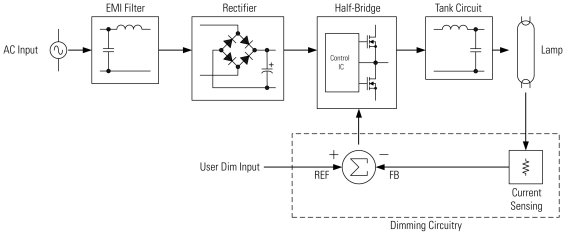
electronic ballast circuit block diagram (Figure 1) includes the ac
line input voltage (typically 220 Vac/50 Hz or 120 Vac/60 Hz), an EMI
filter to block circuit-generated switching noise, a rectifier and
smoothing capacitor, a control IC and half-bridge inverter for dc-ac
conversion, and the resonant tank circuit to ignite and run the lamp.
The additional circuit block required for dimming is also shown. This
circuitry includes a dimming reference signal, a lamp-current sensing
and feedback signal, and a summing circuit for closed-loop control of
the lamp current.
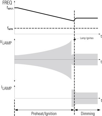
Figure 1. Block diagram of dimming electronic ballast. The lamp requires a current to preheat the filaments, a high-voltage signal for ignition, and a high-frequency ac current to maintain operation during the running mode. To fulfill these requirements, the electronic ballast circuit first performs a low-frequency ac-dc conversion at the input, followed by a high-frequency dc-ac conversion at the output. First, the ac line voltage is full-wave rectified with the output of rectifier peak-charging a capacitor to produce a smooth dc bus voltage. The dc bus voltage is then converted into a high-frequency, 50% duty-cycle, ac square-wave voltage using a standard half-bridge switching circuit. The high-frequency ac square-wave voltage then drives the resonant tank circuit and becomes filtered to produce a sinusoidal current and voltage at the lamp. During pre-ignition, the resonant tank is a series-LC circuit with a high Q-factor. After ignition and during the running mode, the tank is a series-L, parallel-RC circuit with a Q-factor somewhere between a high and low value depending on the lamp dimming level. When the CFL is first turned on, the control IC sweeps the half-bridge frequency from the maximum frequency down towards the resonance frequency of the high-Q ballast output stage. The lamp filaments are preheated as the frequency decreases and the lamp voltage and load current increase (Figure 2).
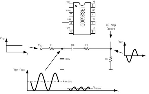
To dim the fluorescent lamp, the frequency of the half-bridge is increased, causing the gain of the resonant tank circuit to decrease and therefore the lamp current to decrease. A closed-loop feedback circuit is then used to measure the lamp current and regulate the current to the dimming reference level by continuously adjusting the half-bridge operating frequency. IRS2530D Operation The IRS2530D dimming control IC includes the feedback control circuit described above, as well as all of the necessary functions to preheat and ignite the lamp and to protect against fault conditions such as open-filament failures, lamp non-strike and mains brown-out. The dimming function is realized by combining the ac-lamp-current measurement (Figure 3) with the dc reference voltage at a single node. The ac lamp-current measurement across the sensing resistor RCS is coupled onto the dc dimming reference through feedback capacitor CFB and resistor RFB.
Figure 3.
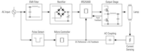
IRS2530D ac+dc dimming control method. The feedback circuit regulates the valley of the ac+dc signal with respect to the COM ground reference as the dc dimming level is increased or decreased by continuously adjusting the half-bridge frequency. This causes the amplitude of the lamp current to then increase or decrease for dimming. If the dc reference is increased, the valley of the ac+dc signal will increase above COM and the feedback circuit will decrease the frequency to increase the gain of the resonant tank. This will increase the lamp current, as well as the amplitude of the ac+dc signal at the DIM pin until the valley reaches COM again. If the dc reference is decreased, the valley will decrease below COM. The feedback circuit will then increase the frequency to decrease the gain of the resonant tank until the valley reaches COM again. Four-Level Switch-Dimming Ballast The block
diagram of the four-level switch-dimming ballast includes an EMI
filter to block ballast-generated switching noise, a full-bridge
rectifier and smoothing dc bus capacitor, and the IRS2530D dimming
control IC, a switching half-bridge and resonant tank circuit to
preheat, ignite and run the lamp, a microcontroller to set and store
the dimming level, and a pulse detection circuit to detect on/off of
the ac input voltage (Figure 4).
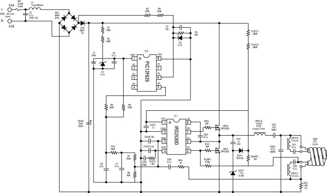
Figure 4. Block diagram of four-level switch-dimming ballast. The full application circuit is shown in Figure 5. The lamp arc current is detected through RCS after ignition and coupled onto a dc reference voltage to provide an ac signal with a dc offset at the DIM pin of IC1. During DIM mode, the IRS2530D adjusts the oscillator frequency in order to maintain the amplitude of this feedback signal and control the lamp current for dimming. The
voltage at the VCO pin of the IRS2530D sets the frequency of the HO
and LO gate-driver outputs. Capacitor CPH is used to program the
frequency sweep time for preheat and ignition of the lamp. At
turn-on, the voltage at the VCO pin will ramp up from 0 V causing the
frequency to decrease from the maximum frequency down to the minimum
frequency. As the frequency continues to fall towards the resonance
frequency of the tank circuit, the lamp voltage increases until the
lamp ignites. The lamp arc current begins to flow and a feedback
signal is produced at the current-sense resistor RCS. If ignition
fails, then the IRS2530D will shut down, going into a low VCC
current-fault mode.
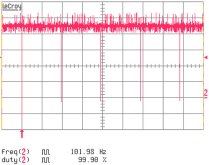
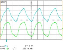
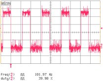
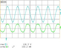
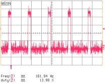
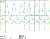
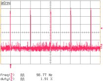
Figure 5. Schematic of four-level switch dimming circuit. The microcontroller (IC2) generates a square-wave voltage at pin 5 that is RC-filtered to produce the dc dimming reference voltage at the DIM pin. The microcontroller generates a fixed-frequency signal with four separate duty-cycle modes for 100%, 66%, 33% and 10% dim levels. The higher the duty cycle, the higher the DIM pin voltage and the higher the brightness level. Pin 6 of IC2 is connected to the ac line input voltage through a fast delay circuit allowing IC2 to detect fast on/off cycles of the ac line input. The VDD supply capacitor C1 is large enough to allow IC2 to continue to run for more than one second after the ac line has been removed. When the ac line is switched off, IC2 detects this rapidly and starts a timer. If power is restored within one second, the output square-wave duty-cycle is reduced and the dimming level is reduced by one step. If the dimming level was already at minimum then it will cycle back to maximum. If the ac line is removed for more than one second, the dimming level will not change. After VDD has discharged below the minimum operating voltage of IC2 the microcontroller will shut off. Figure 6 shows the microcontroller PWM output for each dimming level and the corresponding waveforms for lamp voltage and current.
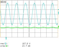
Figure 6a-d. Microcontroller PWM output at pin 5 (red waveform, 1 V/div, 5 msec/div), lamp current (green waveform, 200 mA/div, 10 µsec/div) and lamp voltage (blue waveform, 100 V/div, 10 µsec/div) at each dimming level. The
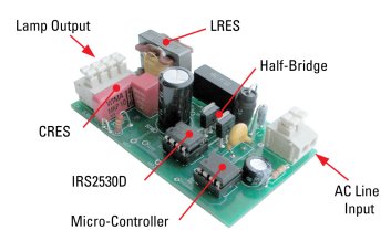
complete reference design (Figure 7) shows the through-hole
components mounted on the top-side and the surface-mounted components
on the bottom side (not shown). The board is a two-layer design with
a very small form factor for driving a 26-W fluorescent lamp.
Figure 7. IRPLDIM5E 4-level switch-dimming ballast reference design.
The IRS2530D dimming control IC enables a simple and low-cost solution that can be used for a wide variety of dimming applications. The complete ballast control, dimming feedback loop and fault protection are included in the IC, so few external components are needed. This simplification of the ballast circuitry allows designers to focus their creativity on developing the different types of dimming interfaces required for each new application. The four-level switch-dimming circuit described in this article is only one application where dimming can be achieved without additional wiring. There are many other dimming applications for various end-lighting uses. In each case, only the interface circuit needs to be designed such that it generates the correct dc reference voltage to the dimming control IC. For more information on the IRS2530D or the four-level switch dimming circuit, consult the IRS2530D datasheet and the IRPLDIM5E reference design, which are available online at www.irf.com. About the Author
Prior to that, Tom was employed by Knobel Lighting Components in Switzerland where he designed dimmable electronic ballast systems for a variety of applications. Tom holds a BSEE degree from California State University, Northridge and a Master’s degree in ASIC design from University of Rapperswil, Switzerland.
For further reading on power conversion in lighting applications, see the How2Power Design Guide, and search the Application category and the Lighting subcategory.” |
||||||||||||||||||
 Since
joining International Rectifier (IR) in 1996, Tom Ribarich has been
the director of IR’s Lighting IC Design Center where he is
responsible for developing control ICs for the global lighting
market, including fluorescent, halogen, HID, LED and LCD backlighting
applications.
Since
joining International Rectifier (IR) in 1996, Tom Ribarich has been
the director of IR’s Lighting IC Design Center where he is
responsible for developing control ICs for the global lighting
market, including fluorescent, halogen, HID, LED and LCD backlighting
applications.