
Exclusive Technology Feature
ISSUE: October 2009
|
Debunking Transformer Performance Myths by Steven M. Sandler and Danny Chow, AEi Systems, Los Angeles, California. In this article we intend to dispel three common myths regarding transformers, and more generally, magnetic coupling.
To provide the proof that these myths are false, three transformers were constructed. Each transformer included only two windings, with 15 turns on each winding. A series of measurements were made for each of the three transformers. All of the measurements were made using one piece of test equipment, OMICRON Lab’s Bode-100 portable vector network analyzer.1 The measurements for each transformer were:
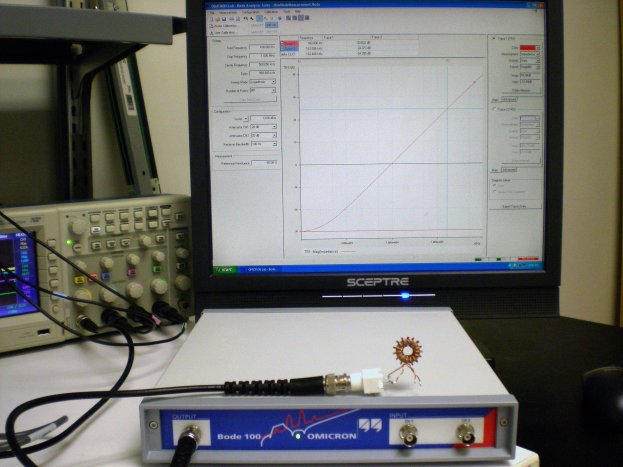
This series represents many more measurements than are actually necessary to assess transformer performance as it relates to the three myths. However, we wanted to show three different methods of assessment, all yielding similar results. Same Turns Ratio, Different Winding Configurations The picture in Figure 1 shows the three wound transformers. One transformer was wound bifilar, with two wires, covering the entire core (360 degree coverage). A second transformer was wound with windings on opposite sides of the core, each in a sector that is approximately 30 degrees. The final transformer was wound with one winding covering the entire core (360 degrees) and the second winding on top of the first, and covering a sector that is approximately 30 degrees of the core. The Bode 100 was calibrated to a BNC jack and the transformer windings were soldered directly to the BNC, as shown in Figure 2. This figure shows the inductance measurement being performed.
Figure 1. The three transformer samples.
Figure 2. Test setup showing the inductance measurement. Measuring Turns Ratios However, before taking readings on the inductance values of each of the transformer windings, the equipment in Figure 2 was used to measure each transformer’s turn’s ratio in both directions. The first measurement showed the ratio as the secondary voltage divided by the primary voltage (Vsec/Vpri), while the second measurement recorded the primary voltage divided by the secondary voltage (Vpri/Vsec). In Figures 3 and 4 these measurements are shown for the bifilar transformer sample.
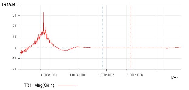
Figure 3. Turns ratio of the bifilar transformer, measured as gain = Vsec/Vpri.
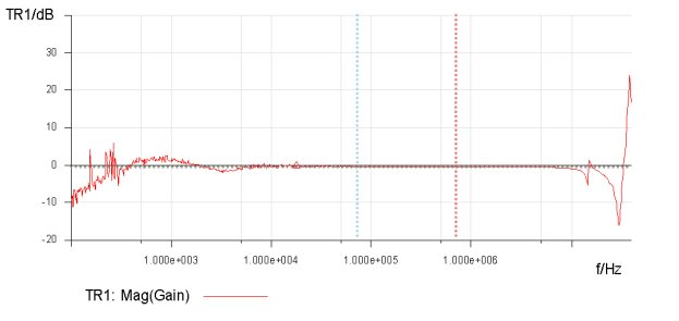
Figure 4. Turns ratio of the bifilar transformer, measured as gain = Vpri/Vsec. The result in Figure 3 yielded an average measurement of -0.140 dB for a turns ratio of approximately 0.985. Figure 4, which shows Vpri/Vsec, is slightly different, with an average measurement of -0.316 dB or a ratio of 0.964. This is slightly different, but still close to the forward measurement. So, the bifilar-wound transformer sample has a turns ratio of 0.985 in one direction and 0.964 in the other direction. Similar measurements were performed on the other two transformer samples with the results presented later in the article. Measuring Inductance The next measurement was a measurement of the primary inductance with the secondary open.
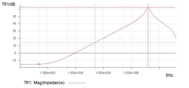
Figure 5. Measurement of winding 1 (primary) inductance with open secondary. The impedance of 14.671 dB at a frequency of 50.184 kHz was 5.4 ohms reactive, which corresponds to an inductance of 17.17 µH. Similarly, the measurement of winding 2 is shown in Figure 6.
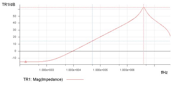
Figure 6. Measurement of winding 2 (secondary) inductance with open primary. The impedance of 14.679 dB at a frequency of 50.184 kHz is 5.42 ohms reactive, which corresponds to an inductance of 17.19 µH. These two inductance measurements were also made with one winding shorted, in order to directly measure the leakage inductance. This method assumes that the shorted winding effectively shorts the core. Figure 7 shows the result of the first of these measurements, measuring the inductance of winding 1 with winding 2 shorted.
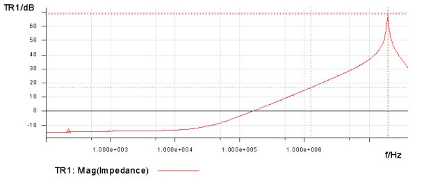
Figure 7. Measurement of winding 1 inductance with winding 2 shorted. The measurement of 16.735 dB at 1.256227 MHz results in a leakage inductance of 870 nH. Similarly in the opposite direction, the measurement is shown in Figure 8.
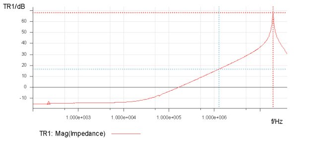
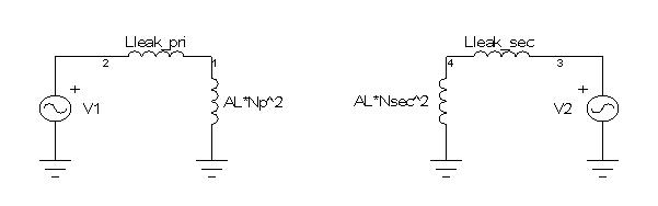
Figure 8. Measurement of winding 2 inductance with winding 1 shorted. The measurement in Figure 8, 16.706 dB at 1.256227 MHz, results in a leakage inductance of 867 nH. The core used for these three transformers is a 55120-A2 MPP core, which has an AL value of 72mH/1000T2. The inductance of 15 turns is, therefore, 16.2 µH. The core is marked +2, which means that the core has an AL value that is 2% above nominal or 73.44 mH/1000T2. Using this marked inductance reference, the core inductance is 16.52 µH. The equivalent circuit for the transformer is shown in Figure 9.
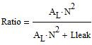
Figure 9. Simplified model of the two-winding transformer. Looking at the simplified model in Figure 9, we can see that the turns ratio of the unloaded transformer (open circuit windings) is:
And it is also seen from the figure that the measured inductance of any winding is the sum of the two inductances:
And lastly, if the core is effectively shorted, the remaining measurement is the leakage term of the winding. Using the first test transformer as an example, the leakage is solved as:
And using the second measurement the results are computed as:
The third measurement, which attempted to measure the leakage directly, resulted in a leakage inductance of 870 nH. Note that this measurement is greater than the other two. This is due to the inability to completely short the core, and the inability to create a zero impedance short across the winding. This is a significant point, because it shows that this is the least accurate measurement, and yet it is the most common method specified for the measurement of leakage inductance. Either of the other two measurements is superior for accurately determining the leakage inductance. Without showing the details of the other measurements, the results are summarized in Table 1. Table 1. Summary of measurements.
It is interesting to note that in the case of the two 30 degree windings, the measurements are also symmetrical, meaning nearly the same in both directions, though the turns ratio is no longer 1, but now is 0.73. This reduction is due to the voltage divider that is created by the mutual inductance and the leakage inductance, and exacerbated by the high leakage inductance of the winding technique. The asymmetrical winding results in asymmetrical results, meaning that the inductance of the winding is different in the two measurement directions, as is the turns ratio, which is nearly 1 in one direction, and substantially lower in the other direction. Analyzing the Findings We can make several conclusions from these simple tests. First, we have proven that while the AL value is a significant contributor to the inductance, it is not the only contributor. It represents the mutual portion of the inductance. The leakage inductance can also represent a significant portion of the inductance of a single winding. Second, we can conclude that the leakage inductance is not a measure of the coupling of one winding to another, but of one winding to itself. A single winding contains a leakage inductance. Third, we can conclude that the turns ratio of the transformer is not simply N1/N2, nor is it the same, as measured in the two possible directions. Again, the leakage term plays a large role. How large a role is dependent on the magnitude and location of the individual leakage terms. Of course, we have also learned that the winding strategy plays a large role as well, and while we have shown these results for two windings, the implications are the same, though exponentially more complex, as the number of windings is increased. Reference: 1. The Bode 100 is a portable Vector Network Analyzer covering the frequency range from 1 Hz to 40 MHz. It is available from OMICRON Lab (www.omicron-lab.com). About the Authors: He is responsible for worst case
circuit analysis of power, RF,
He is
responsible for
reliability engineering analysis
For further reading on magnetic component design, see the How2Power Design Guide, and search the Design Area category and the Magnetics subcategory.” |
|||||||||||||||||||||||||||||||||||||||||||||||||||||||||||||||||||||||||||||||||||||||||||||||||||||||||||||||||||||||||||||||||||
 Steve Sandler is the
founder and CTO of AEi Systems, LLC.
Steve Sandler is the
founder and CTO of AEi Systems, LLC.  Danny Chow is a
Senior Engineering Specialist for AEi Systems, LLC
Danny Chow is a
Senior Engineering Specialist for AEi Systems, LLC